

Result:
Reinforcement Summary:
Ah = 0.00 mm2, horizontal
Checks:
- a/d = 0.00 ≤ 1.0
-
Nu = 0.00 kN
≤ Vu
- Vu shall not exceed of smallest of:
- φ 0.2 f'c (bw) d = 0.00 kN
- φ (3.3 + 0.08 f'c) bw d = 0.00 kN
- φ 11 (bw) d = 0.00 kN
- ε = 0.00000
< 0.004 [R1]
Governing values:
λ = 1.00, concrete weight factor
μ = 1.4 λ = 1.40, friction coefficient
β1 = 0.00, concrete stress block factor
Nu = 0.00 kN, design axial force
fy = 0.00 MPa (flexure & tension)
fyv = 0.00 MPa (shear friction)
Reinforcement computation:
-
Axial Reinforcement
An = Nu/(φfy)
An = 0.00 mm2 -
Shear Friction Reinforcement
Avf = Vu/(φμfyv)
Avf = 0.00 mm2 -
Flexure Reinforcement [R2]
Mu = Vu(a) + Nu(h-d)
Mu = 0.00 kN-m
Af = 0.00 mm2 -
Required Main Reinforcement
As shall be the largest of:
As = 0.00 mm2- Af + An = 0.00 mm 2
- (2/3) Avf + An = 0.00 mm 2
- 0.04(f'c/fy)bw d = 0.00 mm 2
-
Required Horizontal Reinforcement
Ah = 0.5 (As - An)
Ah = 0.00 mm2
Background:
Description
A corbel is a short cantilever projecting out from a column, a wall, or the side of a beam. A corbel is designed to support another member, usually a beam or girder, but may also be used to support a slab. ACI 318 restricts the term “corbel” to a member having span-to-depth ratio which is less than or equal to 1.0. Corbels are widely used in precast concrete construction.
This technical background discusses the requirements for the design of a reinforced concrete corbel in both metric version ACI 318M-14 and the US customary unit version ACI 318-14 of the code. Formulas and terms are primarily expressed in metric units with the equivalent US unit enclosed in square brackets [ ]. The online calculator allows the engineer to select the desired unit.
Geometric Requirements
Chapter 16.5 of the ACI code specifies the provisions for the design of brackets and corbels. Corbels are commonly trapezoidal-shaped but may also be rectangular. For trapezoidal-shaped corbels, the outer depth at the edge of the corbel should have minimum dimension of 0.5 x (effective depth) as depicted in the cover image. The span-to-depth ratio a/d should not exceed 1.0. This is the limit of the tests that were conducted in the formulation of equations.
Loading Limitations
For normal-weight concrete, according to Section 16.5.2.4, the nominal vertical load Vu/φ should not exceed the smallest of:
- 0.2f’cbwd [ 0.2f’cbwd ]
- (3.3 + 0.08f’c)bwd [ (480 + 0.08f’c)bwd ]
- 11bw d [ 1600bwd ]
For light-weight concrete, according to Section 16.5.2.5, Vu/φ should not exceed the smallest of:
- (0.2 – 0.07a/d)f’cbwd [ (0.2 – 0.07a/d)f’cbwd ]
- (5.5 – 1.9a/d)bwd [ (800 – 280a/d)bwd ]
For convenience in the online calculation, the terms above are multiplied by the strength reduction factor φ and compared directly with Vu. The strength reduction factor φ is taken as 0.75 as per Table 21.2.1(f) applicable for brackets and corbels. The reduction factor of 0.75 is used for flexure, axial, and shear-friction strength evaluation.
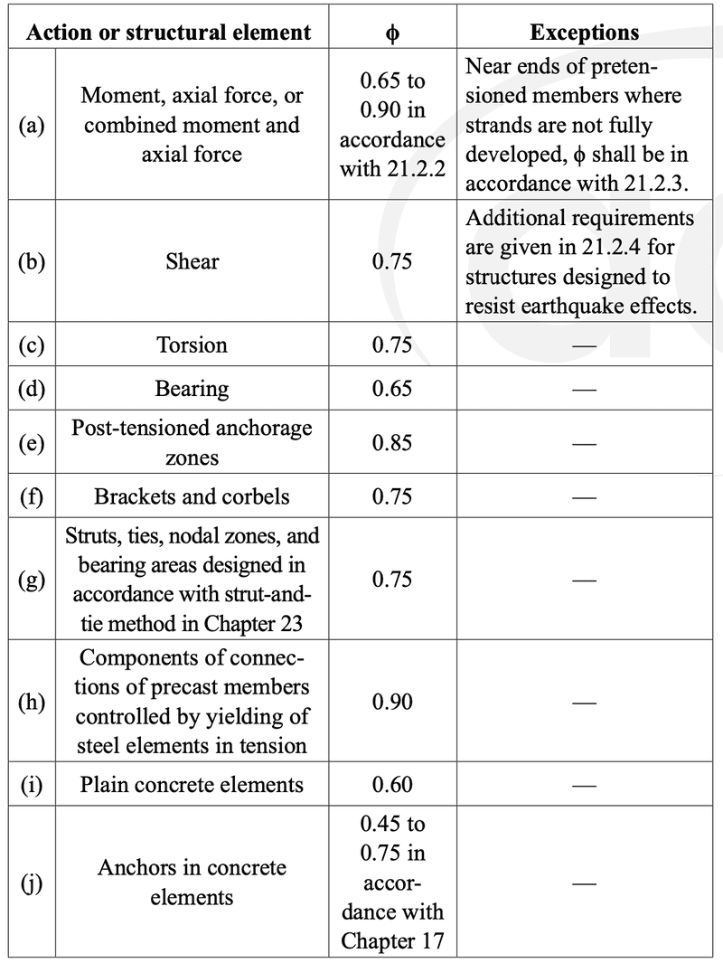
Strength Reduction Factors
In addition, the following load limitations should be checked:
- Maximum horizontal force: Nu ≤ Vu — Section 16.5.1.1
- Minimum horizontal force: Nu ≥ 0.2Vu — Section 16.5.3.5
The minimum horizontal force may be ignored if there are other means to prevent the tensile forces from being transferred into the corbel, such as providing horizontally sliding bearing supports. The online calculator gives the option to ignore the minimum Nu=0.2Vu, e.g. you may use 0 as input value.
Design Property of Materials
The design strength of reinforcement is capped to maximum value of fy = 550 MPa [80 ksi] for flexure and fyv = 420 MPa [60 ksi] for shear-friction as per Table 20.2.2.4a.
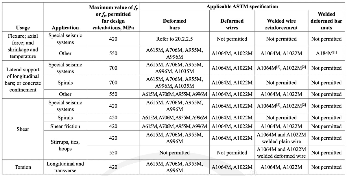
Limit of non-prestressed deformed reinforcement

Limit of non-prestressed deformed reinforcement
Reinforcement Requirements
-
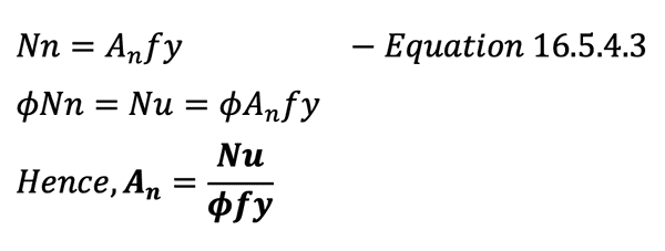
Axial Tensile Reinforcement
The required reinforcement to resist tension alone is given by Equation 16.5.4.3:
-
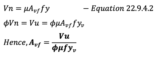
Shear Friction Reinforcement
According to Section 16.5.4.4, shear-friction reinforcement should be determined from Section 22.9 where Equation 22.9.4.2 is given:
-
Flexure Reinforcement
The calculation of flexural reinforcement is governed by the basic principles of flexure where at equilibrium between the compressive force in concrete and the tensile force in reinforcement, the maximum strain in the extreme concrete fiber is 0.003. At this state, the section achieves its ultimate moment capacity. Section 22.2 of the code describes the assumptions for the analysis of moment capacity of sections.
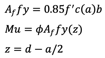

These three equations lead to a quadratic equation whose solution yields to the required flexural reinforcement:


Equation to directly calculate the required reinforcement
as a function of Mu, f’c, fy, b and dThis online corbel calculator checks the level of strain of the reinforcement at ultimate moment with a section reinforced with area equal to Af. Although it is not required by the ACI code for corbel design, the author believes it is prudent to limit the strain due to flexure to 0.004, similar to non-prestressed beams (refer to Section 9.3.3). It should be noted that the strength reduction factor of 0.75 is used all throughout the corbel design even though the code requires as small as 0.65 reduction factor when the section is compression-controlled.
By limiting the steel strain to a minimum of 0.004, it is ensured that the reduction factor never dips below 0.75. The user is referred to Table 21.2.2 for the applicable reduction factors. However, this calculator does not invalidate the design if the recommended minimum strain is not achieved. In most likely cases, this does not govern anyway.
-
Governing Reinforcement
After calculating the reinforcement required for axial force, shear-friction and flexure, the main reinforcement is taken as the largest of the following:
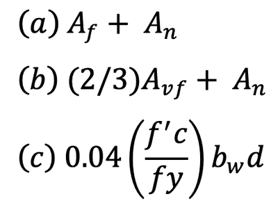

Main corbel reinforcement as per Section 16.5.5.1 The horizontal reinforcement is computed as per Section 16.5.5.2:
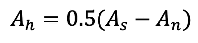

The value of
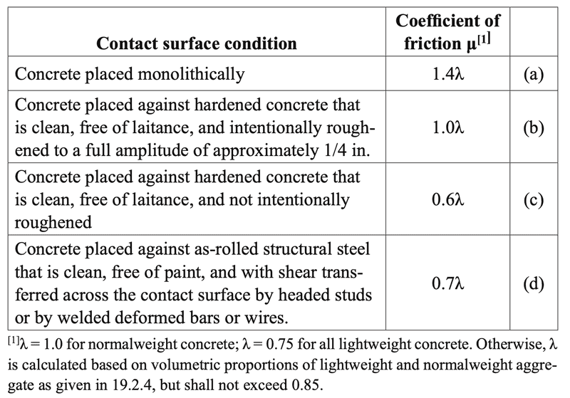
Coefficients of Friction
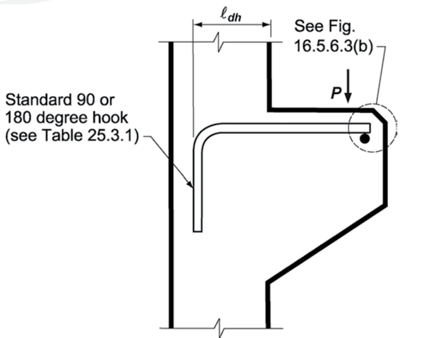
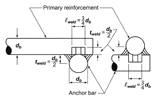
Detailing
The corbel reinforcement should be detailed in accordance to Section 16.5.6. It must be ensured that the reinforcement are properly anchored both in front and at back of the corbel. Refer to some details extracted from ACI 318-14.
I hope you find this tool useful! Please bookmark this page by pressing CTRL+D. Comments and suggestions are very much welcome. I tried to make this calculation tool as accurate as possible but if you find any errors, please don’t hesitate to contact me at [email protected].